Tuesday, May 10, 2016

Final Blog Post

Since many children at the Child Study Center don't wash their hands properly, we decided to create a hand washing aide. It consists of a pressure sensor, a light-up sign depicting the different steps of the hand washing process, and rotating hands. When a child steps on the floor sensor, the picture of the first step, rolling up one's sleeves, is lit up. After 5 seconds, the next picture lights up, and so on. When the scrubbing step is reached, motorized hands begin to rotate, mimicking the scrubbing motion. After the last step, the child has five seconds to step off the mat before the process restarts.

Timeline of Our Project

Week 1
We gave a short presentation in class of our two project ideas, the heart timer and the hand washing aide. We chose to work on the hand washing aide. 

Week 2
We came up with a detailed plan for our project and presented our proposal to Becky. We used her questions and concerns to revise our plan. 

Week 3 
We chose and ordered our materials and worked on foamcore rotating hands and an LED circuit. 

Week 4
We soldered the music shield but then ran into problems with it, the LEDs, and the Velostat. We presented a very rough prototype to Becky at the KSC.

Week 5
We got our Velostat and LEDs working, decided to give up on the music maker, built our mat and sign, and added finishing touches, 

Pictures and Videos of Our Final Product


Conclusion

I really liked our final design. We initially thought using the box was less than ideal, but now I think it's pretty nifty. The Arduino, batteries, and wires are stashed away inside, protecting them from water splashes. When the batteries die, the teacher can simply remove the lid and replace them. Overall, I think the design looks very well put together and it's hard to tell that we created it from random(ish) things we found around the lab. We were really bummed that we didn't have time to get the music maker working, but we made a lot of progress in the final week, and the product is still useful as is. If we had more time, we could work on the music, but the music shield adds $35 to the product cost and might not be worth it. If we had more time, it'd be interesting to work on a way to hang the box on the wall so that it would still be easy for the teacher to remove and replace the batteries. 

Tuesday, May 3, 2016

Final Project Final Week-Glue and Tape Are Our Best Friends

This week was incredibly productive and exciting.

We were having a problem with our LEDs where around the 4th loop through the system, it'd get stuck on one LED. We found out the problem was that millis() was getting too big for our variable type. We had declared previousMillis (the variable that is set to millis() at the end of every loop) to be an int, which can only store values up to 32,767. Once millis() reached 32,767, previousMillis() couldn't update anymore, so it'd get stuck on the last LED. We changed previousMillis() to an unsigned long, which can handle values up to 4,294,967,295. This means that the program could run for 1193 hours, or 49.7 days, before getting stuck. This won't be a problem, however, because the device will be switched off at night, and when it's switched back on in the morning, millis() will reset to 0.

We also worked on our Velostat this week. We realized we'd set it up wrong last week and needed to attach it just like a potentiometer so we could read values from it. After fixing the circuit, we got a reading of 0 whether the Velostat was compressed or not. We had decided to give up and try to use buttons or a photocell instead, but then Amy pointed out a line in the tutorial code that we had overlooked. We added this line to our code, and the Velostat began working! The values didn't range from ~0 (max pressure) to ~1023 (no pressure), the way they did in the product tutorial, however. They ranged from ~0 to ~100, so the Velostat was less sensitive than the advertising made it seem to be. However, we don't need to differentiate between different amounts of pressure for our project, we just need to be able to tell whether or not someone is standing on the sensor. The Velostat is fine for this purpose. After some testing, we settled on a value of 50. A reading of less than 50 means the Velostat is being stepped on, and greater than 50 means it's not being stepped on.

Next, we made a mat. We used the most waterproof yoga mat we could find and cut two 50 squared in. pieces. We sandwiched the Velostat square in between them and hot glued them together. Then we drew a little pair of feet on the top of the mat with a paint pen to indicate to the children that they should step on the mat. Since we had wires coming out of the mat to connect the Velostat to the Arduino, we wrapped them with electrical tape to turn them into a single cord.

The next problem was our Servo hands. We wanted to edit our code so that the motion would look more like hand washing than waving. Originally, our code had the Servo rotate from 60 to 120 degrees. We decided that a third of this rotation would be a good amount. However, when we changed the code, it still rotated from 60 to 120 degrees. We remembered reading that the delay controlled how long the Servo took to complete the rotation. We had a delay of 1000. We thought that since we wanted the Servo to rotate a third as much, we should divide the delay by three. We changed it to 330, and that did the trick.

Next we had to laser cut hands to replace our cardboard prototypes. We were able to automatically trace a hand outline we found online in Corel and print that. Our biggest problem was how to attach the hands to the Servo. After deconstructing the Servo and exploring different avenues such as piano wire and pegs and slots, we decided it would be easiest to hot glue the front hand and cut a slot out of the back hand that would allow it to slide onto the Servo. Hot gluing the front hand worked perfectly fine. We used a file to rough up the contact area between the hand and the Servo so that the glue would work better. It's very secure, and since there won't be any force pulling on the hand, it shouldn't come off the Servo. We did run into a bit of trouble with the back hand. We wanted to make the slot a tight fit so that it wouldn't wiggle or fall off the Servo. Therefore, we made the width of the slot slightly smaller than the width of the Servo and planned to file it if necessary. This plan worked out fine at first, but eventually it turned out that the fit was too tight, and the hand snapped in half. We had to print a new hand, this time making the slot a loose fit and hot gluing it onto the Servo.

The only problem we couldn't solve this week was the music maker. It turns out that we somehow permanently altered the shield after connecting the Servo to it, and it wouldn't work anymore. Unfortunately, we decided to remove the music component from our project.

The last step was setting everything up and making it look pretty. We wrapped our box in green vinyl to conceal the circuit inside. We lined the edges of the vinyl with blue tape to keep them from peeling. We drilled two holes in the side of the box so that we could put the on/off switch on the outside of the box. After looping the cords through the holes, we zip-tied them together tight on the inside of the box so that the switch wouldn't move. We then covered the holes with vinyl on both sides in order to reduce the chances of water getting inside the box. Lastly, we had to attach the Servo to the box. We hot glued a lego to the bottom of it in order to give it a flat surface, and then we glued it to the box. Since it was glued to the vinyl instead of thee actual box, the movement of the hands caused it to wiggle. We had to cut the vinyl around the Servo, scrape off the vinyl and glue, and then glue the Servo back onto the actual box. Now it barely wiggles at all.

Here's our final, perfectly working code! It's been a long time coming. Below the code are some some close-up pictures of various components, and finally, a video of our working final product!


Sunday, April 24, 2016

Final Project Week 4 - 99 Problems and We Can't Fix One

This week we received the materials we ordered and incorporated them into our prototype.

We started with the music shield. We soldered the male headers to the shield so that we could connect it to our arduino. There was one section that we accidentally soldered on facing the wrong direction, so we had to borrow some tools from the physics lab to remove the headers and re-solder them in the right direction.

Next, we tried to get our hand washing song playing. We downloaded the shield's library and edited the code as instructed. The instruction manual didn't explain how to connect the speakers, but we figured they went inside the blue terminal blocks. When we ran the code, the music played, but it was very quiet, and changing the volume in the code had no effect. We also had trouble with the speaker wires falling out of the terminals, so we thought we might not have connected them correctly. We thought the screws in the terminals were supposed to be tightened onto the wires to hold them in place, but the provided wires were too thin. Amy instructed us to solder thicker wires onto the speakers, and those stay in the terminals just fine. We asked her for help with our volume issue, but when we tried to demonstrate the problem, the song would no longer play at all.


After troubleshooting the music issues and not getting far, we moved onto the rest of the circuit.  We got could get our LEDs to go through the pattern once when the button was pressed, but then on the second loop, the first LED would light up and the system would get stuck like that. We also got our servo to turn on only when the button was pressed, but it wouldn't follow the pattern we wanted it to. We wanted it to rotate back and forth through a set arc, but its behavior was erratic; it would rotate through different arcs at different times.

Next we tried out our Velostat with a single LED. The LED definitely got brighter when we applied pressure to the Velostat, but when no pressure was applied, the LED was still on. For our project, we need the LEDs, music, and servo to be completely off when no pressure is applied to the Velostat, because we don't want our system to be constantly running and driving the teachers crazy. We tried applying varying amounts of pressure, using varying amounts of Velostat, and using different resistors, but we still got the same results.


We didn't begin constructing our sign, but we thought we could use a clear plastic box for it. The front side could have the pictures (printed on copy paper) behind it, and the arduino, shield, and all the wires could go inside the box for protection. The hands could sit on top, and the speakers could be attached to either side. 

On Friday we went to present our prototype to the Becky at the CSC. We showed her the LEDs and Servo running through the program once when the button was pressed. We decided to leave the music component out since it would've been so hard to hear. We didn't get as far as we were hoping for our presentation, but based off the erratic behavior we'd seen from our system, we were glad we could get 3/4 outputs to perform adequately even once. 

While at the CSC, we had the chance to check out the bathroom again, take pictures, and begin thinking about where our system would be mounted. Instead of making our own pictures for the sign, we plan on asking Becky if she can send us a copy of the hand-washing sign already up in the bathroom so we can use pictures the children are familiar with. Next week we need to work on getting our song to play again, fixing the volume issue with our speakers, getting our Servo to follow the pattern we want, and figuring out how to get the program to run more than once without the system freaking out. We also need to laser cut our hands, build the box/sign, make our poster, and pretty much have our final product in working order by May 3rd. Let's go!

Final Project Week 3

This week we ordered materials and began working on our prototype.

On Tuesday we cut out some foamcore hands and connected them to motors with tape. We programmed them so that they would rotate back and forth. We plan on building a lego stand and figuring out a better way to connect the hands to the motors. Amy pointed out that we can laser cut the hands instead of 3D printing them since it's cheaper and there's no functional reason why they need to be 3D printed.

We also began to work on a code to get a few LEDs to light up repeatedly in a pattern, but then we set that aside to focus on ordering all the materials we needed.

We had planned on using a force sensor that actually measures the weight on it so we could determine if a child or adult was standing on it, but we couldn't find a reasonably sized and priced sensor online. We realized that we could use a button instead. Pressing the button, no matter the weight, would cause the program to run, so we could just instruct adults not to step on it.

However, since the button is so small, we'd have to build a larger platform for the child to stand on that would simultaneously press the button. We thought about using a squishy material like yoga mat for the base of the platform and cutting a hole for the button, then putting a hard material like a sheet of plastic or wood on top. When a child stepped on the platform, the mat would compress and the hard sheet would press the button.

We also considered two sheets of hard material that are hinged on one side, with a button/buttons in between the sheets on the unhinged side. Stepping anywhere on the platform would press the button(s). We didn't like this idea as much because the platform wouldn't be perfectly level and it would move, so it could be dangerous for the kids. However, we weren't sure if the yoga mat idea would work. Luckily, we didn't have to think about it for long.

Amy found an inexpensive material ($3.95) called Velostat that comes by the square foot (big and durable enough that we wouldn't have to build much of a platform) and changes resistance depending on the pressure applied. We could connect this material to our circuit and it would act as a resistor. When there was no pressure on it, the resistance would be high, so electricity would not be able to flow through the circuit and power the music, hands, and lights. When stepped on, the resistance would decrease so that electricity would flow and the program would run.


We also needed to order a music shield ($34.95) and speakers. We went with with 8 ohm 0.5 W speakers for $1.50. Lastly, we needed to order a micro SD card to store our song(s) on.


Final Project Week 2

This week we had to present our detailed proposal to Becky. We were hoping to visit the CSC to observe the children washing their hands, but unfortunately they were using hand sanitizer since there was a boil-water advisory.

Last week we had planned to have LEDs on the sink, soap, towels, etc. to represent the various steps in the hand washing process.  We decided it would be easier to make a sign with light-up pictures of each of the steps. This way we wouldn't have wires all over the bathroom.
The sign would be mounted on the wall and have pictures of the six steps:

1. Roll up sleeves
2. Get soap
3. Make bubbles (get water and scrub hands)
4. Rinse hands
5. Turn off water
6. Dry hands

The 3-D moving hands and the speaker would also be connected to the sign somehow so that everything would be in one place. The only thing that would be separate would be the force sensor.

When someone stepped on the feet-shaped force sensor on the ground, the program would only run if they were 50 lbs or less, so that adults wouldn't have to go through the process. The child's weight would trigger the hand washing song, the moving hands, and the light-up sign. When the child moved off the sensor, the program would end.

Goal: Help children remember all the steps in the hand-washing process and wash their hands for the proper amount of time.

Mechanism: 3-D printed, motorized hands will mimic hand washing to remind the children to wash their hands.

Sensing, feedback, and control: The reading from the force sensor determines whether a child or adult is standing by the sink and only initiates the program if it detects a child's weight. The program ends when the force sensor detects no weight.

What do we need to create? The 3-D printed hands and the sign. We also need to build our circuit.

What do we need to order? The music-playing equipment and the force sensor.

After our presentation, Becky had a chance to ask questions and voice concerns:

Will there be a way to mute this if it's quiet time?
We're thinking we can either add a small button to the sign that the teacher can press to mute or turn off the program, or we can add a potentiometer that can be used to control the volume.

What happens if the children splash water on the wires/speakers?
The wires will be insulated with tubing and we can either buy waterproof speakers, mount the speakers high on the wall, or build a protective encasement for them,

What if the children grab the moving hands?
They will be mounted high enough that the children shouldn't be able to reach them.

Will there be multiple songs to choose from so that the teachers won't have to hear one song over and over for months?
We can put multiple songs on the SD card and have the program rotate through them.


Thursday, April 21, 2016

Thermal Systems Part 2

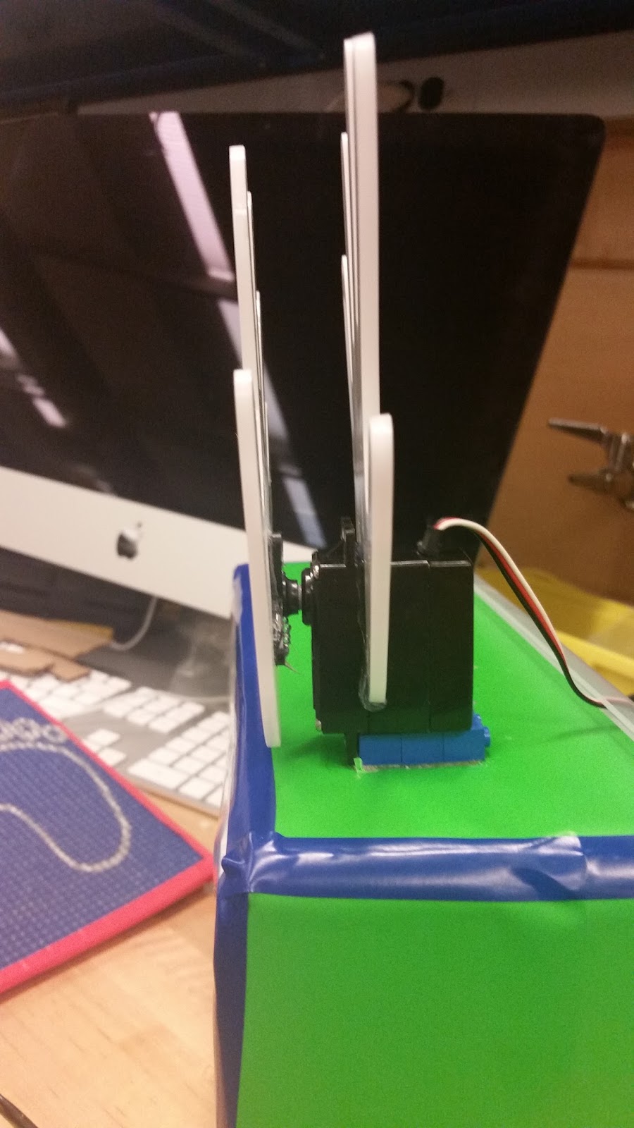
Instead of simulating a cup of coffee heating up, we got to use an actual thermal system today. It consisted of a heater (a 50 ohm resistor) with an 18 V supply, a thermal reservoir, and a temperature sensor.

Deliverable 1
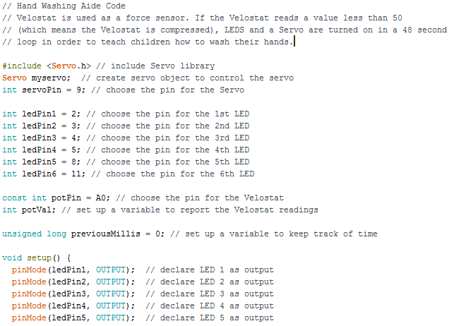
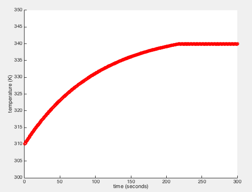
First, we connected our system to the computer and ran a code called test_thermal which turned on the heater for 300 seconds to 100% power and then plotted the temperature as the system warmed up. Here's a picture of that code and the resulting graph.


The next step was to use this graph to find the thermal resistance, Rth, and the heat capacity, C.  We used Rth = delta T / P and the initial (y(1)=310.5602) and final (y(300)=344.6363) temperatures to find Rth = (344.6363 K -310.5602 K)/(6.5 W) = 5.24 K/W.  Then, we used C = P / (dT/dt) to find C. We used data from t=1s to t=11s because that was where the graph could be approximated by a line. We found dT/dt= (T(11)-T(1))/(11-1) = (313.8624 K-310.5602 K)/(11 s-1 s) =  0.3302 K/s. Then we found C = P / (dT/dt) = 6.5 W/0.3302 K/s = 19.68 J/K. The time constant is defined as the time required for the system to reach 63.2% of its final asymptotic value which was about .632*(344.6363 K-310.5602 K)= 21.54 K. By looking at the vector y, we found that the time to reach 310.5602K +21.54K = 332.1 K was about 93 seconds.  Our prediction was tau = Rth*C = 5.24K/W*19.68J/K=103.12 seconds. So, the actual time for the system to respond was less than the expected time.

Deliverable 2
Next, we edited the given code heatsim.m to reflect the newly calculated values, Rth = 5.24 K/W and C = 19.68 J/K, as well as the max power 6.5 W.  We ran this simulation and compared it to to our experimental data.

Here is our modified heatsim.m script.

We wrote this code so that we could plot the simulated and experimental data on one graph. The experimental data is plotted in blue and the simulated data in red. 


The y axis is temperature (K) and the x axis is time (s). In this graph, the experiment looks like it follows the simulation extremely well. 


However, when we zoom in by changing the y axis range from 200-500 K to 300-350 K, we can see that it's not as good a match as we thought. The experimental curve is much bumpier than the extremely smooth simulation curve. The experimental curve is pretty smooth until about 75 seconds, but then it starts to fluctuate and deviate farther from the predicted curve. This is because real-world systems don't operate just as ideal, hypothetical systems do. Us touching the reservoir may have caused some fluctuations, and perhaps the power from the heater and other variables aren't as constant as we thought they'd be.


Deliverable 3
Next, we implemented bang-bang control, so that if the system was below the ideal temperature, the heater would run at max power, and if it was equal to or above the ideal temperature, the heater would not run at all. 

Here's the code for our bang-bang simulation. 


And here's the graph.  It doesn't really look like bang-bang to us. It looks too smooth. We decided to zoom in to see if the "bang bangs" would be more visible. 

In the zoomed in version, you can see that the graph levels off at 340 K around 225 s. 


I edited the code so that the simulation would run for 600 seconds, hoping to see characteristic bang-bang behavior. Unfortunately, it stays at 340 K after 225 s. Once the temperature is equal to or less than 340 K, the power should be set to 0, which would cause the temperature to drop, which would cause the power to be turned back on and the temperature to rise. I'm not sure why the simulation levels out at 340 K.


We moved on to our bang-bang experiment, which turned out as expected. Unlike the previous graph, in the experimental graph you can see the variations in temperature as the power is turned on and off.  


Deliverable 4
Next we implemented proportional control so that the power provided by the heater was proportional to the difference between the actual and desired temperature. The farther from ideal the temp was, the more power would be provided by the heater, and the closer to ideal temp, less power would be provided so that it wouldn't overshoot the ideal temperature. Since we can't have a negative power or a power greater than the heater's capabilities, we set the minimum power to 0 and the maximum to 6.5 W.

We worked on this project over several days, using different sensors (we had to switch them out so that we wouldn't have to wait for one to cool down). The sensor we were using while working on proportional control read 300 K as the ambient temp instead of 310 K, so we changed our code to reflect this. However, our Rth and C values were calculated using an ambient temperature of 300 K. This may be one reason for our issues (which are discussed below our graphs).


K = 0.05

K = 0.2

K=0.5 

As you can see, the greater the K value, the h the higher the final asymptotic temperature. However, even when when we made K ridiculously large, the temperature never reached the ideal of 340 K. The only way we could reach a temp of 340 K is if we added a constant to our power equation. For the graph below, we used the equation P = 5 + k*error with k = 0.5. We thought these constants were optimal, so we also used them for our experiment.

K = 0.5, P = 5 + K*error
Note that this simulation starts from an ambient temperature of 310 K because we'd been using our sensor since we ran the last simulations and it hadn't cooled down completely. 

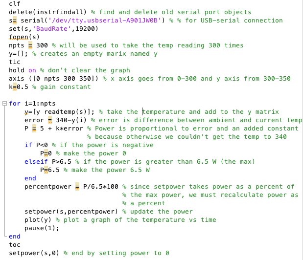
Here is our code for our experimental proportional control. This code differs from the simulation code because the heater power has to be set as a percentage of the max power. Therefore, after we calculated the power, we divided by 6.5 W and multiplied by 100 to find the percentage.


K = 0.5, P = 5 + K*error

Compared to our simulation, this graph seems to level off a bit sooner, around 100 s, and it's also a lot bumpier, due to factors not accounted for in the simulation. However, the simulation is overall a pretty good fit.


Friday, April 15, 2016

Final Project Week 1


This week we needed to brainstorm some project ideas for the CSC and narrow it down to two. We came up with a heart timer and an interactive hand washing program. 


Our first idea, and the idea we were initially most excited about, was the heart timer. One problem the CSC has it that since the kids don't yet understand the concept of time, they're always asking how long is left in an activity or until they get to go home. Becky wanted a way to help the kids answer these questions on their own. The heart would be made out of rows of LEDs and either have buttons representing set times (such as 5 minutes, 15 minutes, half an hour, a half day and a whole day) or a knob such as a potentiometer that could be adjusted to any time. After the time was set by an adult, the rows of LEDs would light up after certain time increments. An example can be seen here. Once the entire heart was lit, the kids would know that the time was up. In order to fulfill the mechanism component of the project, the timer would also have hands or wings that would wave when the time was up. Ultimately, we decided against this project because, although the concept of a child's yearning for their parents as the day progresses being represented by a growing heart made sense to us, it was much too subtle for a child. Instead of coming up with a more concrete way to represent time, we chose to work on the next project.  


Another problem the CSC has is that the children either don't wash their hands at all, don't wash them for long enough, or skip some steps. This project aims to provide a solution to all of those problems. When a child stands on a mat next tot he sink, a force sensor in the mat registers less than 50 lbs of weight and starts the program. A voice will walk the child through the steps of washing their hands, in addition to playing a cute song, such as the one found here. We would also 3D print some hands that would mimic a hand-washing motion to remind the kids to wash. We decided to go with this project because we thought it would be more challenging for us and more useful to the CSC.